Proper C64 S-Video
NOTE: This article addresses the various S-Video signals available from a few different versions of the US NTSC, brown, breadbox Commodore 64. If you have a C64c, C128 or PAL versions etc., I have no idea how much the below information may be of use to you. Proceed with caution.
When my Commodore 1702 monitor recently bit the dust, I found myself struggling with a decision: Invest in another 30 year old tube-based technology or bring the output of my beloved C64 into the 21st century. I chose the latter and couldn't be happier.
Wouldn't you know it? Right in the middle of converting my 200+ collection of C64 floppies to .d64 images, my Commodore 1702 monitor went black and started squealing like a wounded pig. "Well, that's new", I thought to myself. Now what? A quick browse through the pages of eBay revealed a few overpriced, CRT replacements, each of which would cost at least $40 on top of the buy-it-now price to ship. Then it hit me. I have two LCD monitors I'm not currently using. Why not utilize one of them as my C64 monitor? (Nevermind the fact that neither of them have composite or S-Video in) I mean, how hard could it be, right? Converting the C64 output to VGA or HDMI? Turns out my final result wasn't hard at all. It was the process of getting to that final result that nearly ended my life.
Ok. Maybe that was a melodramatic and totally false account of the process. Had I simply paid attention to the few technical books and blog posts I had read regarding making my own S-Video cable, I wouldn't have been so challenged getting a clean signal to my LCD display. The issue I was facing was that there was way too much noise in the signal. Text was almost unreadable and the picture, overall, was just plain annoying to look at. So, I figured, if I had misinterpreted something along the way, surely, at least one other person could have done the same thing.
This post is for you, that one other person.
After deciding to go with an LCD, I had to find a composite or S-Video to VGA or HDMI converter. I found one of each (S-Vid->VGA and S-Vid->HDMI) on eBay and waited a week for one or the other to show up. The VGA converter showed up this past Thursday and thus, started my C64 video odyssey. (S-Video to HDMI arrived. Updated pics below) In addition to explaining how I soldered myself into a corner, I will share a revelation I had after figuring out the noisy signal, that involves making the more common DIN45326 type 270° 8-pin din plug fit perfectly into the uncommon DIN41524 type 262° 8-pin socket, Commodore so wisely chose to use for the C64's A/V port. I suppose they could have gotten by with a 6-pin din, seeing as how pins 7 & 8 aren't even connected internally to anything. However, had they used another 6-pin port, I can imagine the hordes of Commodore tech support calls that would have poured in after thousands of users plugged their IEC devices into their A/V ports, causing that magic puff of smoke, the soul of all electronic devices, to escape their precious C64s. That would be bad. 8-pin makes much more sense to me now.
- S-Video to VGA converter I bought on eBay
- S-Video to HDMI converter I bought on eBay (also takes Composite in as well as L&R audio)
A bit About Audio/Video On The C64:
The audio, chroma & luminance of the C64 are internally mixed together, RF modulated and fed to the RCA jack on the back of the computer. Connect this to the Antenna In on an old television set, choose channel 3 or 4, and the tv would then receive, amplify, filter, and finally, demodulate the signals. This process of encoding and decoding was designed for broadcast video. As such, it degrades the very digital signals of the C64 we are trying to see and hear. If only we could get to the signals before they were mixed together!
At first, Commodore did make some of these signals available at the A/V port. Earlier C64s had a 5-pin A/V port that contained Audio Out, Audio In, Composite Video Out (read as: chroma & luminance combined... important!) and Luminance Out. Most of the technical information I found on the A/V port was for this older, 5-pin solution. All of them said using pin 4, Video Out, was "ok" to be used as the Chroma signal on an S-Video In. That's where I didn't pay complete attention. Using only Luminance with S-Video will get you a pretty clean looking black and white picture, but no color. Adding a composite video signal as if it were Chroma will indeed get you color, but it also comes with some nasty, jpg-like, jaggy artifacts as a bonus. YAY!
Here's the really stupid thing on my part... Later in the C64 lifecycle, Commodore upgraded the 5-pin A/V port with an 8-pin port that contained one, single addition: the Chroma signal on pin 6! (as stated before, pins 7 & 8 are not physically connected to anything internally) Even though I have this 8-pin port on my C64, and even though I knew pin 6 was Chroma, since the 270° 8-pin connector I had didn't fit, I stuck with using one of the hundreds of 5-pin din (MIDI) connectors I had laying around (the DIN41524 180° 5-pin connector pin layout matches the first 5 pins in the 8-pin port). I mean, all the technical data I found said pin 4 was fine... DOH!
Note on video signal levels: It seems the Luminance & Chroma signals on the C64 were not the same voltages as todays S-Video. It works great for the Luma & Chroma input on Commodore monitors, which is why some people refer to it as Commodore video and not S-Video. A few books and blog posts pointed out that adding a 300Ω resister to pin 6 of the updated 8-pin port will make it behave with S-Video systems. The signal is slightly noisy without the resistor and better with. I jumped straight into thinking that that was why I had such a bad signal, so I started playing around with inserting and adjusting a 1k potentiometer on the pin I was using for chroma, pin 4. Didn't make a bit of difference, other than dimming the saturation level of the color. The problem, of course, was because I was using pin 4 video as chroma and not pin 6.
Successful Cable Construction:
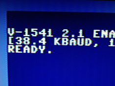
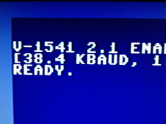
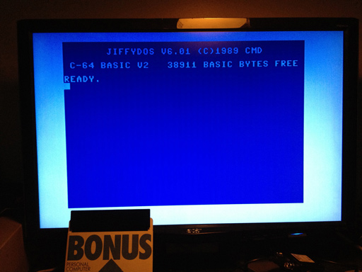
Once it dawned on me to try pin 6, Chroma, I went to work on a custom connector. I started by heating up individual pins of a 5-pin connector and pulling them out of the black plastic housing. I only needed three pins for testing: Luminance (pin1), Chroma (pin6) & Gnd (pin2). I had them sticking gently into the proper pins of the 8-pin port, connected the S-Video connector on the other end of the cable to the S-Video-> VGA converter and turned on the C64. The result? Perfection. Aside from the vertical lines I've read can't be dealt with, all of the jpg-like artifacts were magically gone. It looked pretty close to the Vice C64 emulator. I was ecstatic, to say the least!
Sharing The Revelation:
I instantly logged into commodoreserver.com's chat so I could tell someone who would understand and appreciate that I figured out my video issue. While explaining it to AgentFriday (who so nicely congratulated me on overcoming my stupidity ) I started talking about how I pulled the pins from a 5-pin connector etc.. that the Commodore 8-pin din was the 262° version, unlike the more commonly found 270° version... and then it dawned on me
  that maybe the only difference between the two connectors might happen to be the position of pins 7 & 8, which aren't used anyway. So I grabbed my 8-pin connector that didn't fit, heated up pins 7 & 8 with my soldering iron, pulled 'em out and the connector fit perfectly into the A/V port!!
  I now had a clean way of accessing pin 6, Chroma, from the A/V port and didn't have to wait for a specially ordered connector in the mail.
Pinouts: as seen from the solder side of connectors
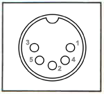
Older 5-pin A/V port
1. Luminance
2. Ground
3. Audio Out
4. Composite Video
5. Audio In
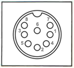
Newer 8-pin A/V port
1. Luminance
2. Ground
3. Audio Out
4. Composite Video
5. Audio In
6. Chroma
7. N.C.
8. N.C.
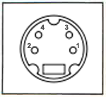
S-Video Connection
1. Luminance Ground
2. Chroma Ground
3. Luminance + Sync
4. Chroma
| S-Video | C64 5-pin | C64 8-pin | |
|---|---|---|---|
| 1 | 2 | 2 | |
| 2 | 2 | 2 | |
| 3 | 1 | 1 | |
| 4 | 4 | 6 | <--300Ω resistor on pin6 of 8-pin port only. |
NOTE: If you have the older, 5-pin DIN, you are stuck connecting pin 4, composite video out, to chroma. This will give you the same crappy video signal in the 'before' pics below. Alpha has a very detailed C64 mod page that shows you where to find the individual chroma signal on the C64's motherboard. Proceed with caution!
Cable Construction: *click images for full sized version
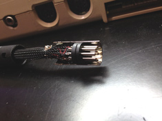
DIN45326 8-pin 270° connector with pins 7 & 8 removed
Now it fits into the DIN41524 8-pin 262° C64 connection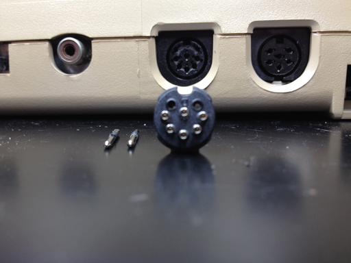
Showing connections for Audio Out, Ground, Luminance.
(twisted both L&R wires in audio cable together to make one connection)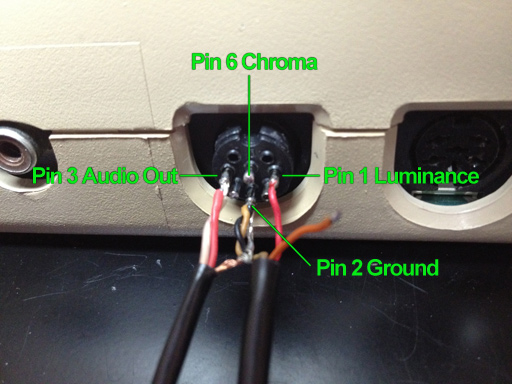
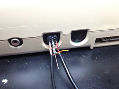
(2) 150Ω resistors in series on pin 6 Chroma - measured 298.9Ω
(didn't have a single 300Ω on hand)
Heat shrink over the two resistors, Chroma wire soldered to the open end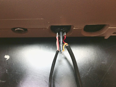
Second heat shrink over the end, covering the soldered Chroma wire
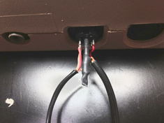
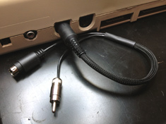
and final cable. I like a single cable coming out, hence the extra sheeth and shrink.
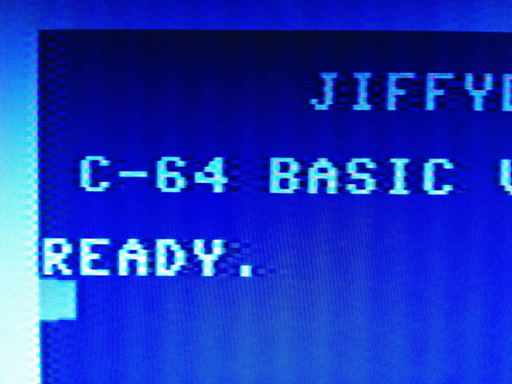
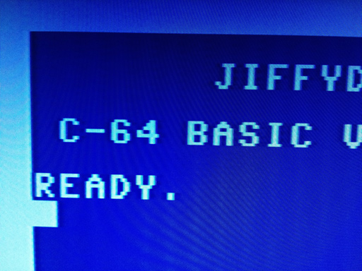
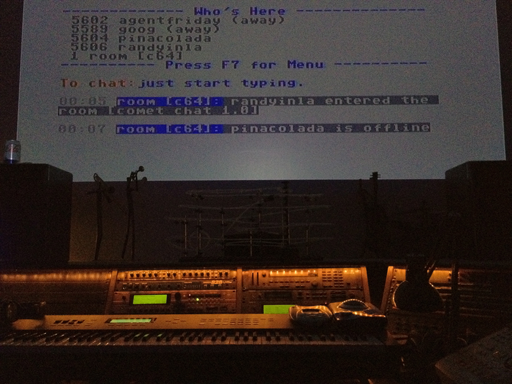
 The graininess is because the overall brightness in the room was pretty dim and this is the best my iPhone's HDR could do. It looks very clear in person. Also, I have no idea what the resolution ends up being on the projector. There isn't a choice for output on the converter.
Whew! That was long!
Hope this helps at least one other person stay sane during their quest for a home-made S-Video connection with their C64.





Leave a Comment
You must be signed-in to post comments.Responses
mish 2/23/2012
I'm looking at something similar.
Which are you seeing better results from? The VGA or the HDMI?
RandyInLA 2/23/2012
The biggest difference was between using pin 4 vs pin 6 for chroma on the S-Video connector. Once it's in S-Video, converting to both the VGA and HDMI look about the same.
dJOS 3/21/2012
Great job on the cable but stretching 4:3 to 16:10 is a cardinal sin!!!! *shields eyes*
RandyInLA 3/22/2012
Actually, the C64's resolution is 320x200, which is exactly 16:10, not 4:3. TV's and monitors back then were only 4:3, so they were the ones doing the compression of the pixels. When I run Vice C64 emulator, the window is 16:10 aspect ratio, not 4:3.
walterg74 5/13/2012
Hi, thanks for this post! I was looking for a while for a nice, clean and well illustrated post on building these for my Commodore 128.
One question though, I read and understood the reason for the 300 ohm resistor, however, I have read on a similar page on video cable construction (which now I can't find grrrr..) that another thing that introduces noise is the "Audio In" pin, and the author solved it (improving the signal) by simply connecting this pin to I *think* it was the GND pin. Have you seen/heard of such a thing? I trying to find the page again to be 100% sure what pin it was connected to, since I only want to do this once and right :)
Cheers!
walterg74 5/13/2012
Ok, while not the original page.. I did find an excellent and detail explanation of the subject, and confirmed you just need to ground the audio in pin:
http://www.bigmech.com/misc/c64mods/noisereduction.html
RandyInLA 4/26/2013
I'll have to try grounding audio in and see if it makes it any better. If so, I'll update my post to include that. Thanks for the tip!
DSProject 4/17/2014
Great article! But I was about to get to it when all the pictures disappeared! Can you link up some new ones?
SteveDay 9/27/2014
In reply to: RandyInLA - 3/22/2012
"Actually, the C64's resolution is 320x200, which is exactly 16:10, not 4:3. TV's and monitors back then were only 4:3, so they were the ones doing the compression of the pixels. When I run Vice C64 emulator, the window is 16:10 aspect ratio, not 4:3."
Yes, the C64 had a resolution equal to 320x200, but the pixels were not square like VGA, SVGA etc. (basically PC monitors have square pixels. Analog video systems do not have square pixels).
You are confusing yourself between the total NUMBER of Pixels (Horizontal x Vertical) versus what the pixels will actually look like when they are displayed on their intended output. It's called "Pixel Aspect Ratio.
What you've done is no better than taking a standard VGA 640x480 image and stretching it to fit on a widescreen monitor - sure, it will fill the screen without any borders, but nothing will look correct!
(If you want to test that theory, adjust your PC monitor controls so the picture looks
RandyInLA 9/27/2014
@DSProject: Sorry! I just realized the images were missing as well. A new top level domain name, 'systems', became available and I couldn't resist updating my walkersystsme.net domain name to just walker.systems. I then updated the doc root of walkersystems.net to point to the one I'm using for walker.systems. Things were fine and somehow the doc root got reset. I have just fixed it and I see the images are back.
@SteveDay: Yes, the pixels are not square.
"What you've done is no better than taking a standard VGA 640x480 image and stretching it to fit on a widescreen monitor - sure, it will fill the screen without any borders, but nothing will look correct!"
This blog post was simply about getting a cleaner s-video signal out of the C64 so that I could THEN convert to VGA or some other resolution and have the best possible looking output on the final display. If you look at the last few before/after images of the LCD display above (maybe they were not displaying when y
RandyInLA 9/27/2014
Wow! Just realized the comments are truncated! THAT sucks!!! wow...
As I was saying...
(Maybe the images above weren't displaying when you made your post and assumed things didn't look right?) You can see the light blue outer border of the C64 screen is wider than the top/bottom. I don't know if the LCD zoomed in a bit or if the VGA converter did, or if anything did. All I know is that nothing looks stretched to me across all the different applications I've run on it and the basic text looks to be the correct pixel aspect ratio. Again, I wasn't trying to fit a square into a rectangle, I was trying to get a cleaner signal before VGA conversion and I believe I have.
Millennium 10/19/2014
Just found your project t today but cannot access pictures. I believe I can go forward with just the text however the photos would be a help for me.
Millennium
RandyInLA 10/19/2014
Thank you for posting your comment, Millennium! I had fixed the broken images a few weeks ago because it was user error. Now, however, it appears the folder I put the images in on my server is not even accessible to me. I am chatting with my hosting support now and hopefully, they will be back shortly.
RandyInLA 10/19/2014
The images are back. Something had happened on the server with my account.
Millennium 10/20/2014
Thank you for looking into the picture issue. All is well. Will let you know how my efforts progress.
Millennium
Millennium 11/28/2014
Hello: Thanks profusely offered. Received my s-video to VGA converter yesterday and my C-64 is performing beyond my expectations via an old Packard Bell monitor. I haven't experimented with any settings on the converter as yet but cannot see how they could possibly be any better. I followed your directions, but did not ground the audio-in pin as suggested in comments.
Cheers
Millennium
Mabo 2/10/2015
Why is pin 3 on the s-video not used?
RandyInLA 2/15/2015
@Mabo: On the s-video pin to C64 pin diagram above (look for "Connections:") , I show pin #3 of the s-video connector (Luminance + Sync) is connected to pin #1 of the C64 (Luminance), regardless if you have the 5-pin or 8-pin connector on the C64.
palcopelo 5/15/2015
Hello to all. RandyInLA, can I ask You to help me? sorry for my English. I have complete the S-Video cable for c64 and in my lcd Samsung with input S-Video the look is great. the trouble is when I connect s-video of c64 in video converter-to-vga. screen appearance is horrible, is full of noise, we say that is just disgusting. surely the problem is in the video converter, any suggestions? in vga converter goes wrong with either the samsung lcd tv that of a CRT monitor philips, identical noise. sin, connected directly to the LCD TV into s-video is perfect. help
Hello and thanks
Sandman192gmailcom 8/13/2015
My Commodore is not the same pin outputs. Form your diagram mine is a little different. Here's what I could test so far on my Commodore 64C. Both black and white for composite and S-video.
1. Right
2. Ground
3. Left
4. U/N
5. Video B/W
6. U/N
7. U/N
8. Video? Is using red right channel and when grounded I get color. Using composite video cable. And no right channel.
When I bought a S-video cable I still got black and white but now it's in stereo.
e5frog 3/1/2016
320x200 resolution has nothing to do with the 4:3 resolution. That area is only the part inside the borders. C64 pixels are also not square...
Visible part (of a full PAL image at least) is something like 384x272 but there's about 403x284 as maximum available image, with normal overscan it's almost never visible.
It surprises me that a 5pin s-video connection wouldn't improve anything, must be related to the screen used.
RandyInLA 3/1/2016
@Sandman192gmailcom Yes, the Commodore 64c is different from the brown breadbox C64. I've had friends who owned one but I have never touched one myself, hence I have no technical info to pass along. Good luck with video out!
RandyInLA 3/1/2016
@e5frog (I recall your name from one of the C64 forums. Welcome!)
However the pixels are shaped, and I know they are not square, when the output is displayed with a 4:3 aspect, everything looks exactly like it does on a typical television screen, which was always 4:3 for US television signal. When the output is forced to 16:9, everything is very noticeably stretched in the horizontal. If you look at my screen capture above for the 16:10 aspect, the outer L&R borders are taking up more space than on a 4:3 US TV. That allows the rest (middle) of the screen to look correct and not stretched. I assume it's my VGA->HDMI converter that is doing that, but it could also be my monitor.
I have never run anything PAL before. I know that PAL video has 576 lines of vertical resolution vs 525 lines for NTSC US Television video signal. There isn't a width listed because each line was a solid scan, void of pixels.
From the NTSC Wiki page: "The NTSC selected 525 scan lines as a comprom
RandyInLA 3/1/2016
@e5frog Re: "It surprises me that a 5pin s-video connection wouldn't improve anything, must be related to the screen used."
The article above points out that the C64 has different A/V ports depending on the year of the C64. For the ones that have chroma & luminance pre-combined onto one pin, and also the fact that the signals don't match today's standard S-Video levels, explains why the resulting S-Video signal via special cable can look bad. It worked on Commodore monitors, which is why people refer to that as Commodore Video and not S-Video. Only the C64s with the 8-pin A/V port provide separate chroma & luminance signals. Again, the article kinda goes into depth on this.
RandyInLA 3/1/2016
UGH! I HATE that this blog has a character limit! Didn't notice it cut off my wiki copy/paste.
"The NTSC selected 525 scan lines as a compromise between RCA's 441-scan line standard (already being used by RCA's NBC TV network) and Philco's and DuMont's desire to increase the number of scan lines to between 605 and 800.[6] The standard recommended a frame rate of 30 frames (images) per second, consisting of two interlaced fields per frame at 262.5 lines per field and 60 fields per second. Other standards in the final recommendation were an aspect ratio of 4:3, and frequency modulation (FM) for the sound signal (which was quite new at the time)."
RandyInLA 3/1/2016
@e5frog: Are you positive the 320x200 only refers to the inner part of the screen, within the light blue borders? I don't recall ever reading anything about the width being able to be set wider than 320 and most games access the full area of the screen, including around the light blue borders visible when booting the machine. I could easily be wrong on this, I just don't recall ever hearing a higher res. Can look at a few C64 programming books when I get home.
RandyInLA 3/1/2016
@e5frog:
Nice page listing details of the various graphics modes of the C64. No where does it say the width is ever greater than 320, therefore it must be 320 pixels from left edge of the screen to the right edge of the screen, including the light blue borders. Whether you are in the correct graphics mode is what allows access to the light blue border area.
http://www.studiostyle.sk/dmagic/gallery/gfxmodes.htm
jdryyz 7/18/2016
I made my own CBM video to S-Video cable yeeeeaaars ago. It did not include a resistor, nor did I perform an audio interference fix. It was just straight wiring of the proper pin signals. It worked fine on the CRT-based TV I used it for back then (a Sony XBR I believe). I am revisiting my C64 after a long time to do some more floppy-disk-to-file archiving and I currently it have it connected to my Sharp 37" LC-37D90U LCD TV via S-Video input. The image does not look right, probably for the reasons you described in this blog. It is kinda hard to describe. I am seeing an image but there is this rapid vertical "shaking" going on. It has the result of making the image look fuzzier than it should be. It almost resembles a video signal in need of "time base correction". I suspect if I connected a cable assembled per your instructions, I could achieve better results. I do have the 8-pin version of the C64, by the way. Question-- can you point to an online source for the parts you have used? I
RandyInLA 7/18/2016
@jdryyz
I don't have any special parts supplier for anything I hack on. I browse eBay, Amazon, Mouser, Jameco etc. There are sometimes great bulk deals on edge connectors/DIN plugs on eBay. Good luck!
jdryyz 7/18/2016
@RandyInLA Like you, I didn't realize the character limit for posts. My original message got cut off right where I mentioned Mouser as someone I have shopped at before but I did not find DIN connectors there.
I was hoping I could be pointed directly to the items you used, but I will just have to use your excellent photos as my guide. I wonder if this guy is building a cable to similar specifications:
http://www.lemon64.com/forum/viewtopic.php?t=61067
Too pricey for me though.
jdryyz 7/21/2016
Looks like the 262 degree 8 pin DINs are not as hard to find now:
http://www.showmecables.com/product/8-Pin-DIN-Male-Solder-Connector-262-Degree-Style.aspx
I have a couple on order.
jdryyz 7/24/2016
Sigh. No go for my newly built cable. Not getting a video signal at all. I confirmed continuity on all connections. I did the extra step of adding the Audio In connection to ground also as described here:
http://www.bigmech.com/misc/c64mods/noisereduction.html
Once thing I did not consider when picking up my 300 ohm resistors is what wattage. I was asked this question at the local electronics store and I was caught off-guard as it was not mentioned on the above link or on this page. I just went with the one I thought matched the scale in the photographs. I believe it was a 1/4 or 1/2 watt. I am guessing that value is not critical for this project given the low voltages but I wasn't going to go with the fatter one I was initially offered.
At any rate, I am not getting a signal. Perhaps I need to be connecting it to a true computer display device (and maybe an s-video to VGA converter while I am at it) and not the HDTV I am trying to use it with. Just to be sure it wasn't the on
jdryyz 7/24/2016
Again, I forgot about the character limit! Hah! Not important, though. I believe I figured it. Will post a follow up soon.
jdryyz 7/24/2016
Yeah, my goof. I switched the Luma & Chroma pins because I missed the line about the correct orientation. :) Working fine now, but sadly, did not solve my problem with the Sharp LCD. I think it is just some quirk with the TV. The cable also works with my home theater AVR and 4K TV. I am going to get some better quality DINs and redo the connections, however. It got a little messy in there after the fix I just did.